2021 PROJECTS

In this post, I will cover some projects I have worked on over the last few months and some projects I have planned for the future.

Bipedal Robot


I am currently busy building a bipedal robot based on this Instructables post by K.Biagini. I used his design as a foundation and added additional components and functionality (such as arms and a Piezo for sound).

I had to modify his 3D models to achieve what I wanted. Here are links to download my modified 3d Models:
– Body Extension (to fit in the extra components) – Link
– Modified Head – Link
– Arms – Link

Here is a list of all the electronic components used:
– 1x Arduino Nano
– 6x micro servos
– 2 x push buttons
– 1x mini toggle switch
– 1x 9v Battery
– 1x ultrasonic sensor (HC-SR04)
– 1x RGB LED
– 1x Piezo

These components are connected as follows:

Pinout configuration of Arduino Nano:

Pin NumberConnected Hardware
2Ultrasonic Sensor Echo Pin
3RGB LED Red Pin
4Push Button 1
5RGB LED Green Pin
6RGB LED Blue Pin
7Push Button 2
8Servo Signal Pin (Right Hip)
9Servo Signal Pin (Right Ankle)
10Servo Signal Pin (Left Hip)
11Piezo
12Servo Signal Pin (Left Ankle)
13Ultrasonic Sensor Trigger Pin
14 (A0)Servo Signal Pin (Left Arm)
15 (A1)Servo Signal Pin (Right Arm)

This is still an in-progress project and is not done, Especially from a coding perspective on the Arduino, but once I have completed this project, I will create a post containing the complete source code.

Rotary Control

I needed a rotary control for another project discussed below, so I decided to build one as per this Post on the Prusa Printers blog. It is based on an Arduino Pro Micro and uses Rotary Encoder Module.

I modified the code available on the Prusa blog to mimic keyboard WASD inputs. Turning the dial left and right will input A and D, respectively. Pressing in the dial control push button will switch to up and down inputs, thus turning the dial left and right will input W and S.
Here is the modified code (Based on Prusa Printers blog post code):

#include <ClickEncoder.h>
#include <TimerOne.h>
#include <HID-Project.h>

#define ENCODER_CLK A0 
#define ENCODER_DT A1
#define ENCODER_SW A2

ClickEncoder *encoder; // variable representing the rotary encoder
int16_t last, value; // variables for current and last rotation value
bool upDown = false;
void timerIsr() {
  encoder->service();
}

void setup() {
  Serial.begin(9600); // Opens the serial connection
  Keyboard.begin();
  encoder = new ClickEncoder(ENCODER_DT, ENCODER_CLK, ENCODER_SW); 

  Timer1.initialize(1000); // Initializes the timer
  Timer1.attachInterrupt(timerIsr); 
  last = -1;
} 

void loop() {  
  value += encoder->getValue();

  if (value != last) { 
    if (upDown)
    {
    if(last<value) // Detecting the direction of rotation
        Keyboard.write('s');
      else
        Keyboard.write('w');
    }
    else
    {
      if(last<value) // Detecting the direction of rotation
        Keyboard.write('d');
      else
        Keyboard.write('a');
    }
    last = value; 
    Serial.print("Encoder Value: "); 
    Serial.println(value);
  }

  // This next part handles the rotary encoder BUTTON
  ClickEncoder::Button b = encoder->getButton(); 
  if (b != ClickEncoder::Open) {
    switch (b) {
      case ClickEncoder::Clicked: 
        upDown = !upDown;
      break;      
      
      case ClickEncoder::DoubleClicked: 
        
      break;      
    }
  }

  delay(10); 
}

I use the rotary control with a Raspberry Pi to control a camera pan-tilt mechanism. Here is a video showing it in action:

I will cover the purpose of the camera as well as the configuration and coding related to the pan-tilt mechanism later in this post.

Raspberry Pi Projects

Raspberry Pi and TensorFlow lite

TensorFlow is a deep learning library developed by Google that allows for the easy creation and implementation of Machine Learning models. There are many articles available online on how to do this, so I will not focus on how to do this.

At a high level, I created a basic object identification model created on my windows PC and then converted the model to a TensorFlow lite model that can be run on a Raspberry pi 4. When the TensorFlow lite model is run on the Raspberry Pi, a video feed is shown of the attached Raspberry Pi camera, with green blocks around items that the model has identified with a text label of what the model believes the object is, as well as a numerical percentage which indicates the level of confidence the model has in the object identification.

I have attached a 3inch LCD screen (in a 3D printed housing) to the Raspberry Pi to show the video feed and object identification in real-time.

The Raspberry Pi Camera is mounted on a pan-tilt bracket which is controlled via two micro servos. As mentioned earlier, the pan-tilt mechanism is controlled via the dial control discussed earlier. The pan-tilt mechanism servos are driven by an Arduino Uno R3 connected to the Raspberry Pi 4 via USB. I initially connected servos straight to Raspberry Pi GPIO pins. However, this resulted in servo jitter. After numerous modifications and attempted fixes, I was not happy with the results, so I decided to use an Arduino Uno R3 to drive the servos instead and connect it to the Raspberry Pi Via USB. I have always found hardware interfacing significantly easier with Arduino and also the result more consistent.

Here is a diagram of how the servos are connected to the Arduino Uno R3:

Below is the Arduino source code I wrote to control the servos. Instructions are sent to the Arduino through serial communication via USB, and the servos are adjusted accordingly.

#include <Servo.h>
#define SERVO1_PIN A2
#define SERVO2_PIN A3

Servo servo1;
Servo servo2;
String direction;
String key;
int servo1Pos = 0;
int servo2Pos = 0;

void setup()
{
  servo1Pos = 90;
  servo2Pos = 90;
  Serial.begin(9600);
  servo1.attach(SERVO1_PIN);
  servo2.attach(SERVO2_PIN);

  servo1.write(30);
  delay(500);
  servo1.write(180);
  delay(500);
  servo1.write(servo1Pos);
  delay(500);
  servo2.write(30);
  delay(500);
  servo2.write(150);
  delay(500);
  servo2.write(servo2Pos);
  delay(500);
  Serial.println("Started");
  servo1.detach();
  servo2.detach();
}

String readSerialPort()
{
  String msg = "";
  if (Serial.available()) {
    delay(10);
    msg = Serial.read();
    Serial.flush();
    msg.trim();
    Serial.println(msg);
  }
  return msg;
}

void loop()
{
  direction = "";
  direction = readSerialPort();
  //Serial.print("direction : " + direction);
  key = "";

  if (direction != "")
  {
    direction.trim();
    key = direction;

    servo1.attach(SERVO1_PIN);
    servo2.attach(SERVO2_PIN);

    if (key == "97")
    {
      if (servo2Pos > 30)
      {
        servo2Pos -= 10;
      }
      servo2.write(servo2Pos);
      delay(500);
      Serial.print("A");
    }

    else if (key == "115")
    {
      if (servo1Pos < 180)
      {
        servo1Pos += 10;
      }
      servo1.write(servo1Pos);
      delay(500);
      Serial.print("S");
    }

    else if (key == "119")
    {
      if (servo1Pos > 30)
      {
        servo1Pos -= 10;
      }
      servo1.write(servo1Pos);
      delay(500);
      Serial.print("W");
    }

    else if (key == "100")
    {
      if (servo2Pos < 150)
      {
        servo2Pos += 10;
      }
      servo2.write(servo2Pos);
      delay(500);
      Serial.print("D");
    }

    delay(100);
    servo1.detach();
    servo2.detach();
  }

}

On the Raspberry Pi, the following Python script is used to transfer the rotary control input via serial communication to the Arduino:

# Import libraries
import serial
import time
import keyboard
import pygame

pygame.init()
screen = pygame.display.set_mode((1, 1))

with serial.Serial("/dev/ttyACM0", 9600, timeout=1) as arduino:
    time.sleep(0.1)
if arduino.isOpen():
    done = False
while not done:
    for event in pygame.event.get():
    if event.type == pygame.QUIT:
    done = True
elif event.type == pygame.KEYDOWN:
if event.key == pygame.K_s:
    arduino.write('s'.encode())

if event.key == pygame.K_w:
    arduino.write('w'.encode())

if event.key == pygame.K_a:
    arduino.write('a'.encode())

if event.key == pygame.K_d:
    arduino.write('d'.encode())
time.sleep(0.5)

arduino.Close();
print ("Goodbye")

The next thing I want to implement on this project is face tracking using TensorFlow lite with automated camera movement.

Raspberry Pi Zero W Mini PC

I built a tiny PC using a Raspberry Pi Zero W combined with a RII RT-MWK01 V3 wireless mini keyboard and a 5 inch LCD display for Raspberry Pi with a 3D printed screen stand.


It is possible to run Quake 1 on the Raspberry Pi Zero following the instructions in this GitHub, and it runs great.

Raspberry Pi Mini Server Rack

I have 3D printed a mini server rack and configured a four Raspberry Pi Cluster consisting of three raspberry Pi 3s and one Raspberry Pi 2. They are all networked via a basic five-port switch.

I am currently busy with a few different projects using the Pi cluster and will have some posts in the future going into some more details on these projects.

I developed a little Python application to monitor my different Raspberry Pis and show which ones are online (shown in green) and offline (shown in red).

The application pings each endpoint every 5 seconds, and it is also possible to click on an individual endpoint to ping it immediately. The list of endpoints is read from a CSV file, and it is easy to add additional endpoints. The UI is automatically updated on program startup with the endpoints listed in the CSV file.

Here is the Python source code of the application:

import PySimpleGUI as sg
import csv
import time
import os
from apscheduler.schedulers.background import BackgroundScheduler


def ping(address):
    response = os.system("ping -n 1 " + address)
    return response


def update_element(server):
    global window
    global layout
    response = ping(server.address)
    if response == 0:
        server.status = 1
        window.Element(server.name).Update(button_color=('white', 'green'))
        window.refresh()
    else:
        server.status = 0
        window.Element(server.name).Update(button_color=('white', 'red'))
        window.refresh()


def update_window():
    global serverList
    for server in serverlist:
        update_element(server)


class server:
    def __init__(self, name, address, status):
        self.name = name
        self.address = address
        self.status = status


serverlist = []

with open('servers.csv') as csv_file:
    csv_reader = csv.reader(csv_file, delimiter=',')
    line_count = 0
    for row in csv_reader:
        if line_count == 0:
            line_count += 1
        else:
            serverlist.append(server(row[0], row[1], 0))
            line_count += 1

layout = [
    [sg.Text("Server List:")],
]

for server in serverlist:
    layout.append([sg.Button('%s' % server.name, 
                    button_color=('white', 'orange'), 
                    key='%s' % server.name)])

window = sg.Window(title="KillerRobotics Server Monitor", 
                    layout=layout, margins=(100, 30))
window.finalize()
scheduler = BackgroundScheduler()
scheduler.start()

scheduler.add_job(update_window, 'interval', seconds=5, id='server_check_job')

while True:
    event, values = window.read()
    if event == sg.WIN_CLOSED:
        scheduler.remove_all_jobs()
        scheduler.shutdown()
        window.close()
        break
    elif event in [server.name for server in serverlist]:
        scheduler.pause()
        update_element([server for server in 
                         serverlist if server.name == event][0])
        scheduler.resume()

Raspberry Pi Pico

I ordered a few Raspberry Pi Picos on its release, and thus far, I am very impressed with this small and inexpensive microcontroller.

The Raspberry Pi Pico sells for $4 (USD) and has the following specifications:
– RP2040 microcontroller chip designed by Raspberry Pi
– Dual-core Arm Cortex-M0+ processor, flexible clock running up to 133 MHz
– 264KB on-chip SRAM
– 2MB on-board QSPI Flash
– 26 multifunction GPIO pins, including 3 analogue inputs
– 2 × UART, 2 × SPI controllers, 2 × I2C controllers, 16 × PWM channels
– 1 × USB 1.1 controller and PHY, with host and device support
– 8 × Programmable I/O (PIO) state machines for custom peripheral support
– Low-power sleep and dormant modes
– Accurate on-chip clock
– Temperature sensor
– Accelerated integer and floating-point libraries on-chip

It is a versatile little microcontroller that nicely fills the gap between Arduino and similar microcontrollers and the more traditional Raspberry Pis or similar single board computers.
I have only scratched the surface of using the Pico on some really basic projects, but I have quite a few ideas of using it on some more interesting projects in the future.

3D Printing

I ran into some problems with my 3D printer (Wanhao i3 Mini) over the last few months. The First problem was that half of the printed LCD display died, which was an annoyance, but the printer was still usable. The next issue, which was significantly more severe, was that the printer was unable to heat up the hot end.

My first course of action was to replace both the heating cartridge and the thermistor to ensure that neither of those components were to blame, and unfortunately, they were not. After some diagnostics with a multimeter on the printer’s motherboard, I determined that no power was passing through to the heating cartridge connectors on the motherboard.

I ordered a replacement motherboard and installed it, and the 3D printer is working as good as new again. When I have some more time, I will try and diagnose the exact problem on the old motherboard and repair it.
Here are photos of the old motherboard I removed from the printer:

Below are some photos of a few things I have 3D printed the last few months:

2021 PROJECTS

A Tour of Silicon Valley

I recently did a self-tour of Silicon Valley, and as someone who works in the field of technology, it was a fantastic experience.

The first stop of the tour was Apple Park, the Head Quarters for Apple Inc. The only section open to the public is the Visitor Center, which mainly consists of a massive apple store (which was insanely busy as it was 2 days after the iPhone 11 and 11 Pro launched) as well as a sizeable Augmented Reality display of the Apple Park Campus and the famous UFO looking Apple Ring building. This AR display consists of a large model, shown in the photos below, that you can interact with using an iPad Pro which the staff hand out to guests entering the display area. On the iPad Pro graphics are superimposed over the model showing not only a realistic aerial view of the campus but also showing various bits of information relating to the design of the ring building such as how the ring building is designed in a way to take advantage of the environment (wind, etc.) to cool itself in an ecologically friendly manner.

The next stop was the Apple Garage, which is the garage at the house in which Steve Jobs grew up. It is commonly considered the birthplace of Apple. Steve Wozniak (Apple co-founder) has said that this is a bit of a romanticized myth, but it was still great to see.

IMG_9460

Next came the Computer History Museum, a truly amazing museum with items covering the entire history of computers. From the abacus to mainframes and supercomputers to the current day smartphone, the items on display are truly astonishing. Below are some photos and descriptions of some of the items on display.

Numerous Abacuses on display, one of the oldest forms of calculation tools.

A variety of mechanical calculation machines.

IMG_9482

A Curta Calculator, also known as the Pepper Grinder Calculator. One of the most advanced handheld mechanical calculators ever created.

A Selection of IBM Mainframe Equipment.

IMG_9510

A model of ENIAC, the world’s first general-purpose computer.

IMG_9536

A Selection of Fortran Programming Books and Promotional Material.

A PDP-1 Display, Spacewar! one of the first video games ever was programmed on and ran on the PDP-1.

IMG_9551

A 486 DX motherboard.

A display showing the advancement of transistors, microprocessors, silicon wafers, and Moore’s Law.

Various Robots on display. Including expensive toys, industrial robots, and research robots.

Numerous bizarre and unusual computer peripherals on display.

Video and computer gaming displays, with various consoles and games on display.

Apple I, Apple II, Apple Lisa, and Original Macintosh computers.

IBM PC Model 5150 and an Altair 8800.

IMG_9663

A boxed copy of Windows 1.0.

IMG_9667

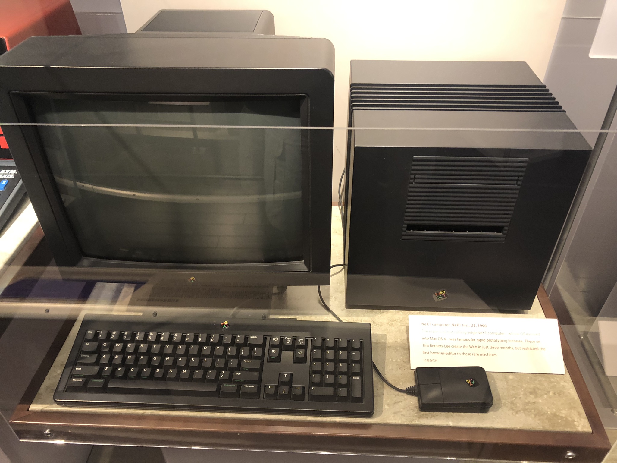
The NeXTcube workstation from NeXt Computers. NeXt computers were founded by Steve Jobs after leaving Apple in 1985, and Next Computers were acquired by Apple when Steve Jobs rejoined Apple in 1997. The NeXTStep Operating system became the foundation for Mac OSX.

IMG_9671

Waymo Self-Driving Car.

IMG_9673

A scale model of the Mars Rover.

World of Warcraft exhibition.

An exhibition showing the rise of MP3s and the rise and fall of Napster.

The next stop after the Computer History Museum was the Googleplex, the massive headquarters of Google. The Googleplex, which is mostly open to the public, has various significant things to see, such as the Android Statue Lawn, where retired Android statues representing previous versions of the mobile operating system are on display. From volleyball courts to Massive Statues to vegetable gardens, it is easy to see why the Google Campus has a reputation as the best working environment. Here are a few photos of the Googleplex.

The last stop in Silicon Valley was Stanford University, a University that amongst its alumni has various famous people. Stanford has a beautiful Campus, as can be seen in the photos below.

A Tour of Silicon Valley

UCTRONICS SMART ROBOT CAR KIT

uctronrobot

The UCTRONICS Smart Robot Car Kit is an easy to build obstacle avoidance robot kit that also allows for direct user control of the robot through either Infrared (using the included remote control) or Bluetooth (an Android App is available on the Google Play Store).

This is a great starter kit as no soldering is required and additionally there is a lot of space on the robot chassis for customization and additions later on. Assembly instructions are provided in full color and takes the builder through the assembly process in a step-by-step manner, which is easy to follow.
A prebuilt Arduino sketch is available for download from the UCTRONICS website to make the assembled robot functional, however nothing prevents the builder from writing their own. This is however one area where I do feel the kit falls short as an educational tool, instead of just providing a prebuilt sketch, it would have been great if a step-by-step guide was provided taking the builder through the process of writing their own sketch, explaining concepts and what is being done and why along the way.
This is however still a great starter kit and I would recommend it for anyone getting started in robotics or Arduino related building.

UCTRONICS SMART ROBOT CAR KIT

SunFounder DIY 4-DOF Sloth Robot Kit

Today we will have a look at a robot kit created by SunFounder. The Sloth is a bi-pedal robot based on the Arduino Nano. It utilises an ultrasonic module for obstacle detection and four servos for movement.

I found the kit to be an easy and fun build that took approximately an hour to complete. SunFounder have uploaded a YouTube video that serves as detailed introductions and assembly tutorial for the robot. It covers the entire assembly process, including the process to test the ultrasonic module as well as all the servos (before assembly), which is a good thing as one of the servos included with my kit turned out to be broken, but luckily I had a replacement servo on hand.

One thing to note is that the robot utilises two 18650 batteries, which after some research turned out to be commonly used in high-end flashlights and e-cigarettes, and are relatively pricey.

The robot can also be powered through the mini USB port on the Arduino (which I did while I waited for the batteries I had ordered to be delivered).

The code for the robot can be downloaded from here on the SunFounder website. Just note that the default code did not work for me as the ultrasound module did not detect obstacles. I rectified this by replacing the following code:

void loop()
{
 	int <span class="mceItemHidden" data-mce-bogus="1"><span class="hiddenSpellError" pre="int " data-mce-bogus="1">tooclose</span></span> = 0; // Define the test times, the initial value is 0
 	for(int a=0; a&lt;5; a++)  //for is a cyclical function and its cyclic times are determined by the second condition in the bracket. Here a&lt;5, a’s initial value is 0. When a&lt;5, run the program in the bracket. After running, a becomes a++ and it means adding 1 to a’s value.
	{
		delay(50); // Delay 50ms
		int din = sonar.ping_in(); // Call the ultrasonic transducer to read the distance that ultrasonic detected.
		if (din &lt; 7 &amp;&amp; din &gt; 0) tooclose++; // The smoothing. The times add 1 when the detect distance less than 7cm and greater than 0cm.
	}

With this:

void loop()
{
	int <span class="mceItemHidden" data-mce-bogus="1"><span class="hiddenSpellError" pre="int " data-mce-bogus="1">tooclose</span></span> = 0; // Define the test times, the initial value is 0
	for(int a=0; a&lt;5; a++)  //for is a cyclical function and its cyclic times are determined by the second condition in the bracket. Here a&lt;5, a’s initial value is 0. When a&lt;5, run the program in the bracket. After running, a becomes a++ and it means adding 1 to a’s value.
	{
		delay(50); // Delay 50ms
		int din = sonar.ping(); // Call the ultrasonic transducer to read the distance that ultrasonic detected.
		if (din &lt; 750 &amp;&amp; din &gt; 0) tooclose++;
	}

I really enjoyed assembling and playing with this little robot and would definitely recommend it to anyone interested in getting started in basic robotics.

SunFounder DIY 4-DOF Sloth Robot Kit

Dev Day 2016

veqjhvgb_400x400

On the Tuesday 27 September 2016 the first Dev Day occurred in Johannesburg South Africa. Dev Day is best described on their twitter page as “A community-owned and driven gathering of technologists, investors, hobbyists, engineers, artists, students and anyone with a strong sense of curiosity”. And I was invited to showcase some of the robots I have been working on. The event was extremely well organised with various people and Maker groups showcasing what they were working on as well as numerous speakers including Uncle Bob (Robert C. Martin). I really enjoyed the event and the experience of showing some of my work and the feedback and questions I received were amazing. It really was a great experience getting to talk and interact with similarly minded people. Many thanks to the organisers for a great event, hopefully one of many to come.

Here are some photos of my stand and the event.

Dev Day 2016

Book Review – Build Your Own Humanoid Robots

Book Cover

The first thing to note is that this book does not cover any Arduino-based robots. All the robots are based on PIC micro-controllers. Also note that this book goes into very low-level detail, even covering the fabrication of your own Printed Circuit Boards.

But even considering the above-mentioned I found this book extremely useful, not because of the electronic sections, but because of the mechanical build sections. 

The book shows exactly what raw materials to buy, what tools you will require and how to assemble the robots chassis and mechanical parts. And all these can easily be incorporated into an Arduino-based robot.

All six projects in the book can also be made to work with an Arduino without too much difficulty, all it will require is a bit of creativity and understanding of Arduino. 

For someone interested in Arduino based robots this book might not be the complete package, but the mechanical sections are some of the best I have ever seen in a book. If you are however interested in PIC-based robotics this book is a must buy.

Book Review – Build Your Own Humanoid Robots

Pololu Zumo 32U4 Robot

zumo32u4

In a previous post I looked at the Pololu Robot shield for Arduino, which was a robot shield on top of which a Arduino UNO R3 plugged into to form a great little autonomous robot.

Today we will be looking at the Pololu Zumo 32U4 Robot, a robot similar in size to the Zumo Robot shield for Arduino, but with quite a few changes. Firstly it no longer requires a separate Arduino board as it has an Arduino compatible micro-controller directly integrated into its main-board. It also has a LCD screen and IR proximity sensors which the previously mentioned robot did not have.

The Zumo Robot shield for Arduino came with 75:1 HP motors which produce average speed and torque. In the new Zumo I am installing 100:1 HP motors which are slower that the 75:1 HP motors but produce a lot more torque (which will be great for pushing in Robot Sumo matches).

Similarly to the Zumo Robot shield for Arduino the robot also has an expansion area that can be used to connect additional sensors and actuators. As with the Zumo Robot shield for Arduino various different operating source code can be downloaded from Pololu website, that changes the robot into anything from a sumo fighter to a line follower or even an auto-balancing robot, to name a few.

I bought the Zumo 32U4 Robot kit, which required assembly (unlike the Zumo Robot shield for Arduino that only required an Arduino to be plugged in). 

Here is a time Lapse of the robots assembly. 

I really like the Pololu Zumo series of robots and find them reliable, easy to develop for and a great deal of fun. There are various options available, from fully assembled to kit form depending what you are interested in.

zumos

And now that I have two, I can finally have some Robot Sumo fights, so expect some videos of that soon.

Pololu Zumo 32U4 Robot

IoT

I am starting an IoT project and wanted to share a little bit.  IoT or the Internet of Things is defined on Wikipedia as “the network of physical objects—devices, vehicles, buildings and other items embedded with electronics, software, sensors and network connectivity—that enables these objects to collect and exchange data. The Internet of Things allows objects to be sensed and controlled remotely across existing network infrastructure, creating opportunities for more direct integration of the physical world into computer-based systems, and resulting in improved efficiency, accuracy and economic benefit;”.  

To learn more I would recommend the book The Internet of Things Do-It-Yourself at Home Projects for Arduino, Raspberry Pi, and BeagleBone Black by Donald Norris. It provides an in-depth technical overview of concepts as well as some projects that can be built. The projects in the book are not particularly exciting but they do a good job at illustrating concepts and methods utilised.

Book

So I am going to be using a Raspberry Pi2 running Windows 10 IoT core, which will be communicating with some Arduino boards.

I am also looking at integrating with Azure Machine Learning to do some interesting things. 

I have not decided on many elements of the final project, but it will involve a robot.

rasp

On a side note, do not try to deploy Windows 10 IoT Core on a SD card using a Mac, it is a huge pain. My main computer I use at home (and for most of my development, blogging, video editing, etc.) is a MacBook Pro and in the end I gave up trying to get the deploy working and used my windows laptop which worked almost instantaneously.

Once I have decided exactly what I want to achieve and made some progress I will post more on this topic.

IoT

Insectbot Mini DIY Kit

InsectMain

I have previously built an Insectbot using instructions from the Internet, but subsequently DFRobot have created a kit that conveniently contains everything you need to build one without the need of finding and buying all the components individually.

InsectBoxOpen

This is a very easy little robot to assemble and is great for beginners, with one exception, the piece of plastic used for the robots head needs to be cut and holes made through, which sounds easy enough…. However do not be fooled, as it is the most brittle and fragile piece of plastic I have ever seen. Not breaking it is nearly impossible. Luckily it can easily be replaced with any other piece of flat plastic, such as a plastic container lid, etc.  

The robot uses a rechargeable battery, which is very convenient and comes with an adapter to charge via USB. 

InsectContent2

Here is a time-lapse video of the robots assembly.

The kit is relatively inexpensive and is a great little kit (with the exception of the plastic used for the robots head) and I would recommend it for anyone interested in getting started. The Beetle board used in the robot is fully Arduino compatible and can be developed for using the Arduino IDE.

A basic version of operating code can be downloaded from the products web page (http://www.dfrobot.com/index.php?route=product/product&product_id=1055#.Vtke2JN97fZ). This can be modified as much as you like to truly make the little robot your own.

Here is a video of the little guy in action. Just take note of one shortcoming, and that is that they really struggle to get traction when walking, so some custom shoes will help (I used some cork from a wine bottle, which I cut into little feet.) 

Insectbot Mini DIY Kit

Book Review – Robot Builder’s Bonanza

Many books have been written on the topic of robot building, ranging from very basic to extremely complex, but I have seldom come across a book that gets the balance right. Robot Builder’s Bonanza by Gordon McComb hits the sweet spot.

robotbook

The book provides a vast amount of detail on the electronics, mechanics and programming required to build a robot. Concepts like movement (for both wheeled and legged robots), sensors (to make your robot perceive its environment and conditions), the pros and cons of different Micro-controllers, as well as many other actuators (that allow the robot to change its environment in some way) are all covered. 

At the start of each section, a brief introduction to the field is given that includes explanations of key concepts (such as resistors and capacitors in the case of the electronics section) to the tools used (such as drills and screws in the case of the mechanical section). The book includes over 100 projects as examples to illustrate the concepts covered.

The book, in both print and content, is of very high quality. It is very clearly written and provides many diagrams, pictures and schematics, making it easy to understand even the more complex topics covered, for example robotic vision, robotic interpretation of sounds or the choice of which micro-controllers to use as your robots’ brain.

I would very highly recommend Robot Builder’s Bonanza to anyone interested in getting started in robot building or even someone who is currently building robots. It is not just a great book for learning the basics and getting started, but it is also a great reference guide to complex topics as well as a source of inspiration.

As far as Robotics books go this is one of the best, do yourself a favour and pick up a copy today.

Book Review – Robot Builder’s Bonanza