Today we will take a detailed look at my Roaming Robot.
Part List:
- Sparkfun Magician Chassis (this includes 2 DC motors)
- 1 x Capacitors 100uF
- 4 x Resistors 220 Ohm
- 1 x Micro Servo
- Seeed Ultrasonic Sensor
- Sharp IR Sensor
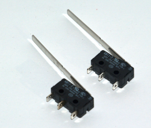
- 2 x Long Arm Trigger Switches
- 1 x LED (ultra bright white)
- 1 x Photo-resistor
- 1 x Arduino Uno R3
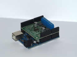
- 1 x Pololu Dual MC33926 Motor Driver Shield
Power supply:
- 1 x 9V Battery (used to power the 2 DC motors through the motor shield)
- 4 x AA Batteries in a battery holder (used to power Arduino and PCB\Breadboard)
The Pololu Dual MC33926 Motor Driver Shield plugs into the Arduino female headers and all connectors shown in below diagrams actually plug into the Motor shield and not directly into the Arduino as shown.
The first diagram shows the wiring for the LED, photo-resistor, trigger switches, and the servo:
The two switches shown are actually the 2 long arm trigger switches.
The circuit shown above is very straightforward. However note the capacitor across the servo power terminals. This is to prevent a voltage drop in the circuit caused by the servo starting to move, which draws more current to start moving than when it is already moving.
The below diagram shows how the Seeed Ultrasonic and Sharp IR sensors are wired:
So the Arduino is wired as follows (through the motor driver female headers):
Analog Pins:
- A0 – this pin is used by the MC33926 Motor shield
- A1 – this pin is used by the MC33926 Motor shield
- A2 – Servo
- A3
- A4 – IR Sensor
- A5 – Photo-resistor
Digital Pins:
- 0
- 1
- 2
- 3 – LED
- 4 – this pin is used by the MC33926 Motor shield
- 5 – Ultrasonic Sensor
- 6 – Right Trigger Switch
- 7 – this pin is used by the MC33926 Motor shield
- 8 – this pin is used by the MC33926 Motor shield
- 9 – this pin is used by the MC33926 Motor shield
- 10 – this pin is used by the MC33926 Motor shield
- 11 – Left Trigger Switch
- 12 – this pin is used by the MC33926 Motor shield
- 13
The Arduino VDD (5V) and GND pins are used to power the PCB\Breadboard.
The Servo acts as the robots’ neck, it can turn the Ultrasonic Sensor in various directions. The Ultrasonic Sensor is used to detect obstructions, which the robot will then avoid, for obstructions too low for the Ultrasonic Sensor to detect the trigger switches will be pressed and the object can then be avoided. The Photo-resistor is used to detect light level and if it is deemed too dark the LED will turn on. The IR sensor is used to detect drops, so that the robot does not fall down a vertical drop, such as a step.
The two DC motors of the Magician Chassis are connected to the Motor shield, the left motor to the two most left screw terminals on the shield and the right motor to the two most right screw terminals on the shield. The 2 middle screw terminals on the shield are used to power the motors; the 9V battery should be connected to them. (Just note that if one or both of the robots’ motors move in the opposite direction than expected, this can be rectified by switching the 2 motor wires around between the screw terminals they are connected to on the motor shield.)
Here is the code used with the Robot (it is written in C and must be deployed on the Arduino):
#include "DualMC33926MotorShield.h"
#include "Servo.h"

#define IR_PIN A4
#define SERVO_PIN A2
#define PING_PIN 5
#define BUMPER_LEFT_PIN 11
#define BUMPER_RIGHT_PIN 6
#define LDR_PIN A5
#define LED_PIN 3
#define IR_DROP 450 //Distance considered a potential drop
#define MIN_LIGHT 300 //Level of light to turn on LED for light

DualMC33926MotorShield md;
const int M1Speed = 300;
const int M2Speed = 300;
int IRDist = 0;
int bpLeft = 0;
int bpRight = 0;
int LDRValue = 0;
const int dangerThresh = 12;// (in cm) used for obstacle avoidance
int leftDistance, rightDistance; //distances on either side
Servo panMotor; //'neck' servo
long duration; //time it takes to receive PING signal

void setup()
{
pinMode(BUMPER_LEFT_PIN,INPUT);
pinMode(BUMPER_RIGHT_PIN,INPUT);
pinMode(LED_PIN, OUTPUT);
}

void moveStop()
{
md.init();
md.setSpeeds(0,0);
}

void moveForward()
{
md.init();
moveStop();
md.setSpeeds(M1Speed,M2Speed);
delay(250);
}

void turnLeft()
{
md.init();
moveStop();
md.setSpeeds(M1Speed,-M2Speed);
delay(250);
}

void turnRight()
{
md.init();
moveStop();
md.setSpeeds(-M1Speed,M2Speed);
delay(250);
}

void moveBack()
{
md.init();
moveStop();
md.setSpeeds(-M1Speed,-M2Speed);
delay(250);
}

int checkDrop()
{
pinMode(IR_PIN,INPUT);
IRDist = analogRead(IR_PIN);
if(IRDist < IR_DROP)
{
return 1; //Drop present (determined with IR distance sensor)
}
else
{
return 0;
}
}

void lightDarkness()
{
LDRValue = analogRead(LDR_PIN);
if(LDRValue < MIN_LIGHT)
{
digitalWrite(LED_PIN,HIGH); //It is dark, turn on the light
}
else
{
digitalWrite(LED_PIN,LOW);
}
}

int checkLeftBumper()
{
bpLeft = digitalRead(BUMPER_LEFT_PIN);
if(bpLeft == HIGH)
{
//HIT!
return 1;
}
else
{
return 0;
}
}

int checkRightBumper()
{
bpRight = digitalRead(BUMPER_RIGHT_PIN);
if(bpRight == HIGH)
{
//HIT!
return 1;
}
else
{
return 0;
}
}

void compareDistance() {
if (leftDistance>rightDistance) //if left is less obstructed
{
turnLeft();
}
else if (rightDistance>leftDistance) //if right is less obstructed
{
turnRight();
}
else //if they are equally obstructed
{
moveBack();
}
}

long ping()
{
// Send Ping pulse
pinMode(PING_PIN, OUTPUT);
digitalWrite(PING_PIN, LOW);
delayMicroseconds(2);
digitalWrite(PING_PIN, HIGH);
delayMicroseconds(5);
digitalWrite(PING_PIN, LOW);

//Get duration it takes to receive echo of Ping sent
pinMode(PING_PIN, INPUT);
duration = pulseIn(PING_PIN, HIGH);

//Convert duration into distance (cm)
return duration / 29 / 2;
}

void loop()
{
lightDarkness();
if(checkDrop() == 1)
{
moveBack();
compareDistance();
}
else
if(checkLeftBumper() == 1)
{
moveBack();
compareDistance();
}
else if(checkRightBumper() == 1)
{
moveBack();
compareDistance();
}
else
{
moveStop();
int distanceFwd = ping();

if (distanceFwd>dangerThresh) //if path is clear
{
moveForward();
}
else //if path is blocked
{
moveStop();

panMotor.attach(SERVO_PIN);
panMotor.write(20); //look right

delay(250);

rightDistance = ping(); //scan to the right
panMotor.write(160); //look left

delay(600);

leftDistance = ping(); //scan to the left
panMotor.write(90); //look to centre

delay(300);

panMotor.detach();
compareDistance();
}
}
}


Reblogged this on ElectronicsTechies and commented:
Great article!!
LikeLike
[…] Roaming robot has recently been giving me some problems, specifically regarding the power distribution between […]
LikeLike